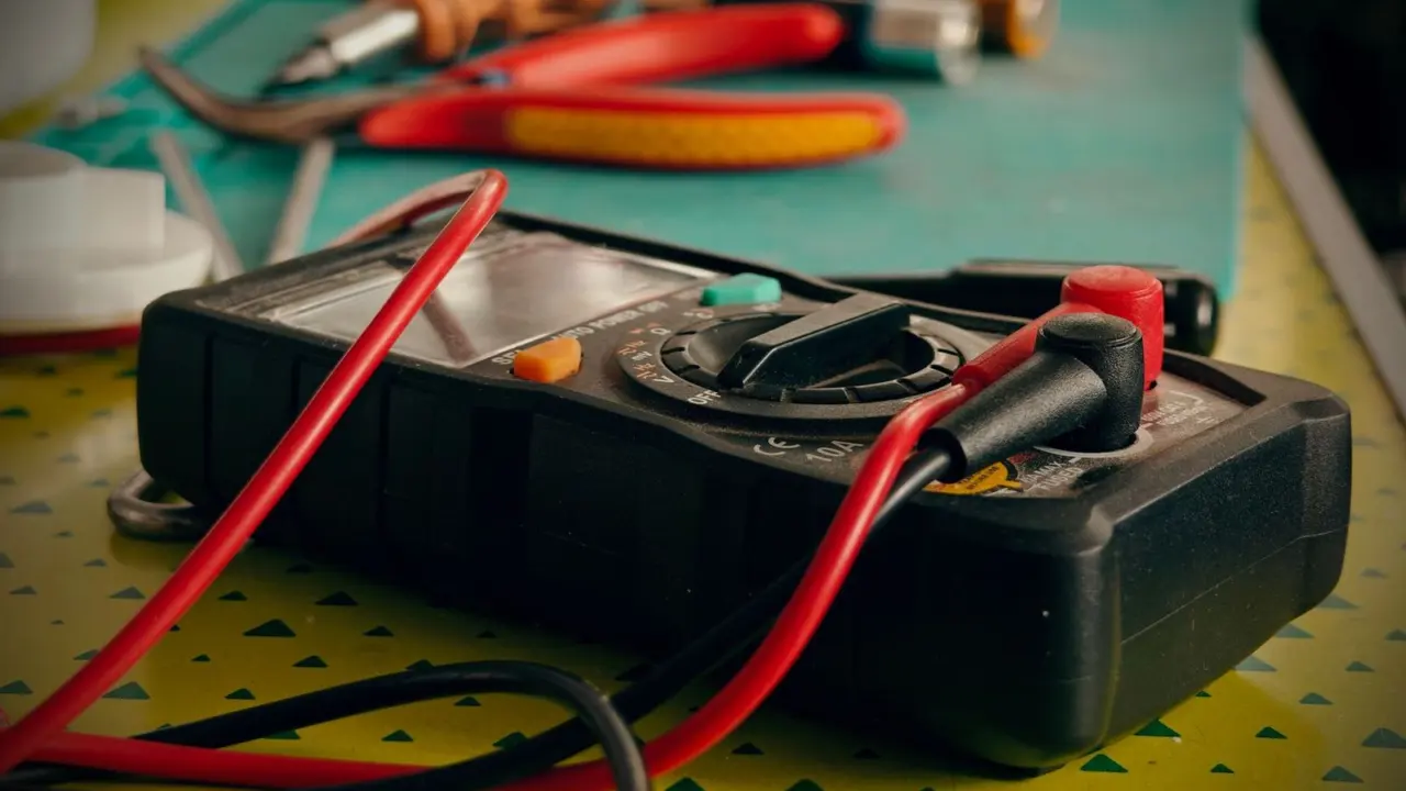
Not sure where to start with a meter and a dead circuit? Here is how to use a multimeter: pick the mode, plug the probes into the right jacks, then measure voltage across the circuit, or resistance and continuity on the part.
This guide sits within the wider topic of electronics repair, and it covers the readings you will use most.
| Item | Value |
|---|---|
| Input resistance of a high-impedance DMM | 1 MΩ to 10 MΩ |
| Input impedance of a low-impedance (Low Z) tester | 2 kΩ to 100 kΩ |
| Peak value of a 480 VAC (RMS) reading | 679 VAC |
| Standard that defines CAT ratings | IEC 61010-1 |
| When DMMs began appearing on the market | Late 1970s |
The figures come from Wevolver’s 31 March 2026 guide and EC&M’s multimeter article. Specifications and standards can change, so check the source before you rely on them.
What a multimeter measures
A multimeter is a single handheld tool that works as a voltmeter, ammeter and ohmmeter. Voltage, current and resistance are the core readings, and EC&M states that all multimeters measure all three. Many models add continuity, capacitance, frequency and diode tests.
You will meet a few types of meter, and the type changes how you read it:
- Digital multimeter (DMM): shows a number on a screen and is by far the most used type. DMMs began appearing in the late 1970s, according to EC&M.
- Analog multimeter: moves a needle across a scale. You must read directly over the needle to avoid parallax error, and a small mirror on the meter face helps you line it up.
- Clamp meter: measures current without breaking the circuit, which makes it useful when opening a connection is impractical or dangerous.
A basic non-contact pen tester only tells you hot or not, as This Old House puts it. A multimeter gives you exact voltage levels, resistance values and current draw, which is what you need to work out why a circuit is misbehaving.
Setting up the meter and probes
A few minutes of setup prevents most bad readings. Work through these steps before you touch the circuit:
- Read your manual. EC&M advises that you familiarize yourself with your meter’s functions, capabilities and ratings before use.
- Turn the selector switch to the mode you need: voltage, resistance, continuity or another function.
- Plug the black probe into the common (COM) jack and the red probe into the jack for the measurement, such as VΩmA.
- Choose the correct jack and range. Wevolver warns that a wrong choice can blow the internal fuse.
- Check that your test leads are rated for the voltage and current you are measuring.
On the jacks, Wevolver explains that separate jacks serve high-current measurements (often labelled 10 A or A), low-current measurements and general voltage or resistance. The red probe goes to the positive side and the black probe to the common or negative terminal.
Most modern DMMs are auto-ranging: the meter detects the value and picks a range for you. Manual ranging still has a place, because locking the range gives a stable reading when noise makes an auto-ranging meter jump.
Measuring voltage, resistance and continuity
Voltage
Voltage is measured across points, while current is measured through a branch. That means you touch the probes to the points on either side of the part or supply you want to check, with the red probe on the positive side and the black probe on the negative side.
Before you probe, it helps to learn how to read a schematic, because the drawing shows which points sit across the part you want to test.
Resistance
For resistance, the meter supplies a known test current and works out the value from it. Because of that, a digital meter can damage sensitive electronics by issuing a small amount of test current, as This Old House notes.
Lead resistance matters on very small values. Wevolver says conventional 2-wire measurements include test-lead resistance, while a 4-wire setup removes it and enables milliohm accuracy.
Continuity
Continuity tells you whether electricity has a constant pathway to flow through, according to This Old House. In practice you use it to find out whether a wire, fuse or joint is intact or whether the circuit is open.
If a continuity check points to a cracked joint, you can read up on how to solder before you rework it.
Staying safe: CAT ratings and a test-the-tester check
Meters are built to a standard that defines measurement categories. Wevolver’s 31 March 2026 guide describes IEC 61010-1 and its CAT levels as follows:
- CAT I: circuits not directly connected to mains, such as battery-powered electronics.
- CAT II: branch circuits that power plug-in loads, such as household appliances and portable tools.
- CAT III: permanently installed equipment such as motor control centres, lighting circuits and industrial wiring.
- CAT IV: measurements at the service entrance or on power lines upstream of the main overcurrent device.
A CAT II meter must never be used where CAT III or CAT IV conditions exist. Match your fuses and test leads to the meter’s category and voltage rating as well.
When you check for power on a normally energized circuit, This Old House quotes a three-step protocol from an electrician with long experience in power stations:
- Check the tester on a circuit you know to be live.
- Check the circuit you will work on.
- Check the tester on the known live circuit again to be sure it is still working.
The same source adds that you should always know the voltage-level rating of your tester.
Do you need a true RMS or high-impedance meter?
Using an average-responding meter when a true RMS meter is needed gives an inaccurate reading, according to EC&M. Distorted waveforms are where it matters, and the same article notes the output of electronic drives is a series of pulses that only a true RMS meter measures accurately.
EC&M also points out a safety detail: a meter reading 480 VAC shows the RMS value, and the peak value of 480 VAC is 679 VAC. Your leads are in contact with that higher peak.
Input impedance is the other spec to know. Wevolver reports that high-impedance DMMs have input resistances of 1 MΩ to 10 MΩ, so they barely disturb the circuit. Low Z testers, at 2 kΩ to 100 kΩ, intentionally load the circuit to remove ghost voltages, but they can trip ground fault circuit interrupters or alter sensitive circuits.
Frequently asked questions
Which jack does the red probe go in?
Show answer
The red probe goes in the jack labelled for the measurement, such as VΩmA, A or +, while the black probe goes in the common (COM) jack. Check your manual for your meter’s exact layout.
Can a multimeter tell me whether a wire is live?
Show answer
Yes, and it gives you the actual voltage rather than only a yes or no. A non-contact pen tester only tells you hot or not, according to This Old House.
Should I use auto-ranging or manual ranging?
Show answer
Auto-ranging is easier, especially for beginners, and suits readings of unknown size. Manual ranging lets you lock the range for a steady reading when noise makes the display jump.
Why is my analog meter reading off?
Show answer
Parallax error is a likely cause: it happens when you view the needle at an angle. Look straight over the needle, or use a meter with a mirror on the scale and line the needle up with its reflection.