Your board dies, a fuse blows, or a power rail won’t come up. Learning how to find a short circuit on a circuit board comes down to three moves: inspect it, measure it, then inject a little current and follow it.
This guide is one part of the wider electronics repair topic on this site, so start there if you want the bigger picture.
| Item | Value |
|---|---|
| Meter sensitivity for resistance checks | Milliohm sensitivity |
| Bench supply current limit while hunting | 100mA to 1A, depending on the board |
| Bench supply voltage limit while hunting | Less than 0.5V |
| Voltmeter resolution when injecting about 500mA | 10uV or better |
These figures come from Altium’s short circuit testing guide and an EEVblog forum thread of community advice. They vary by board and can change, so check the sources before you rely on them.
What a short circuit does to a board
A short circuit happens when a point on the circuit connects to ground when it isn’t supposed to. The current meant to reach its destination gets diverted to ground partway along. iFixit’s microsoldering guide lists the usual symptoms:
- Boot loops
- A device that only sometimes turns on, or doesn’t turn on at all
- A battery that drains too quickly
Shorts have a few common origins. Altium notes they can come from unintentional shorts between nets in the design data, or from defects during fabrication or assembly, as described in its short circuit testing guide. Knowing which is likely helps you decide where to look first.
Prepare the board and inspect it first
Before any probing, disconnect all power. iFixit says its resistance and diode-mode testing is always done with the device disconnected from any power source, including the battery, as explained in the same microsoldering article.
If a fuse blew, find out why. Nuts & Volts says the reason must be determined rather than just replacing the fuse with a bigger one, in its circuit board repair article. The same article says a conformal coating must be removed, at least at a few critical test points, before fault diagnosis can begin.
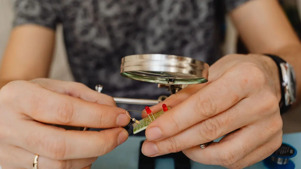
Then take a slow visual pass with a magnifying glass or low-magnification microscope, as Altium recommends. Start at the power supply and work forward. Look for:
- Tin whiskers or solder bridges between pads and joints
- Cracks or blobs of solder
- Poorly plated vias, which Altium says can short layers together
- Brown, burned spots on the solder mask
- Dull solder joints, since good joints look smooth, bright and evenly flowed according to Nuts & Volts
- Leaking, cracked or bulging capacitors
A clean surface doesn’t clear the board. Altium points out that some shorts are internal and produce no burn spots, so they can’t be seen from the surface layer.
Measure resistance with a multimeter
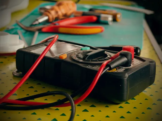
If the eyes find nothing, a multimeter is the next tool. Altium suggests one with milliohm sensitivity and ideally a buzz function that sounds when you probe a short, as covered in its testing guide.
Check between neighbouring pads or traces, where you expect high resistance. A very low reading between two conductors that should be in separate circuits suggests they are bridged. Also probe each supply rail to ground, since that is where most shorts show up.
Diode mode gives a second view. If you need a refresher, read how to test a diode with a multimeter before you start. iFixit’s method compares the reading at a suspect pad with a known-good unit of the same device. As an example it cites pin 9 on an iPhone 11 Pro display connector, which reads around 0.7V drop on working units, per its microsoldering article.
Expect limits. A poster in a BadCaps forum thread argues that locating a short needs something that reads very small resistance values, which a standard DMM cannot do. That is one reason the next method is so popular.
Follow the current with a limited bench supply
When resistance readings tell you only that a short exists, inject current and follow the voltage. Nuts & Volts advises powering the rail with less than the 3.3V or 5.0V it normally needs, limiting the supply current too, and bringing both up slowly, in its repair article.
One EEVblog contributor sets the current limit in the 100mA to 1A range, depending on how chunky the board is, with a voltage limit of less than 0.5V. Another passes 500mA into the shorted rail to find shorted MLCC capacitors on laptop mainboards, and says 10uV resolution or better is needed on the voltmeter, according to the EEVblog thread.
- Connect the supply at the board’s supply and ground connection points, not at the ends of the supply leads.
- Set the voltage and current limits low.
- Measure the voltage along the ground and supply rails across the board.
- Move toward the points whose voltage is closest to the short’s own voltage.
- Near the spot, measure across every component that receives power.
The logic is simple. The thread explains that points on one side of the short sit below its voltage and points on the other side sit above it, so the readings nearest the short’s voltage are physically closest to it.

Do not push harder than the parts can take. A reply in the BadCaps thread cautions that raised voltage should not exceed the maximum voltage withstand of the chip.
Use heat to reveal hidden shorts
A short dissipates power, so heat can give it away. Altium says an infrared camera can show where a large amount of heat is being generated, and advises starting with the lowest current you can so you spot the short before it does more damage.
Nuts & Volts describes a thermal camera as the more sophisticated method. Its simpler alternative is briefly powering the board after spraying it with freezer spray, since the low-resistance area warms first. A forum contributor on EEVblog describes a similar low-cost trick: spray the board with isopropyl alcohol, power it up and see where it evaporates fastest.
Touch is a last resort. Altium’s own author admits the only burn on his board was on the fingers that checked for overheating chips, so use low current and take care.
Interlayer shorts are the hardest. Nuts & Volts warns that you can spend a long, frustrating time locating a single short, particularly an interlayer one.
Narrow it down and confirm the culprit
Schematics speed this up. iFixit calls them extremely valuable for hunting shorts, because they show which rails feed which parts. If you are new to them, see how to read a schematic to trace a rail from its source to every part it touches.
Once you have a suspect area, use elimination. The EEVblog thread suggests unplugging parts until the current draw normalises and testing the removed components one by one. A known-good board helps too, since Nuts & Volts says troubleshooting is much easier when you can compare against one.
After each removal or rework step, re-measure the rail. If the short is gone, you have found the part or joint responsible.
Frequently asked questions
Can a cheap multimeter find a short?
Show answer
It can show that a low-resistance path exists. Some forum users say a standard DMM can’t read very small resistance values, so a milliohm-capable meter or the voltage-following method works better for pinpointing the location.
Should I replace a blown fuse with a bigger one?
Show answer
No. Nuts & Volts says to determine why the fuse blew rather than just replacing it with a bigger one.
What if the short is inside the board layers?
Show answer
Altium notes internal shorts leave no burn spots on the surface. A thermal camera or the voltage-following method is more useful than looking at the board.
Is it safe to feel parts for heat?
Show answer
It can burn you. Altium’s author reports burned fingers from checking chips by touch. Keep the current low, or use an infrared camera instead.