Got a suspect diode on your bench? Here is how to test a diode with a multimeter: set diode mode, red probe on the anode, black on the cathode. A good silicon diode reads about 0.6V to 0.7V, and OL when reversed.
This guide is part of our wider coverage of electronics repair, where each check builds on the last.
| Item | Value |
|---|---|
| Good silicon diode, forward reading | About 0.6V to 0.7V |
| Good diode, reverse reading | OL |
| Germanium diode, forward reading | 0.2 to 0.3 V |
| LED, forward reading | 1.8V to 3.3V, depending on colour |
| Shorted diode, both directions | Close to 0V |
| Open diode, both directions | OL |
These figures come from Starting Electronics and eTechnophiles. They can change between meters and sources, so check the source before you rely on them.
What you need before you start
Before a probe touches anything, turn off power to the circuit. Starting Electronics says to do this before removing or testing any diode.
For the cleanest reading, isolate the diode from the rest of the board. eTechnophiles advises disconnecting or removing it if possible, so no other part of the circuit is connected to it.
Next, find the cathode. Diodes are typically cylindrical with a band or stripe on one end, and the terminal connected to that band is the cathode (-), while the other terminal is the anode (+), according to eTechnophiles.
Gather these before you begin:
- A digital multimeter with a diode-test setting, marked with a diode symbol.
- Test leads, with the red lead in the voltage/ohm port and the black lead in the COM port.
- The diode, powered down and ideally lifted out of the circuit.
Testing a diode in diode mode, step by step
Diode mode is built for this job. It outputs a small voltage, usually around 2V, and measures the forward voltage drop directly, as Starting Electronics explains.
- Switch the circuit off and isolate the diode.
- Turn the rotary dial to the diode symbol.
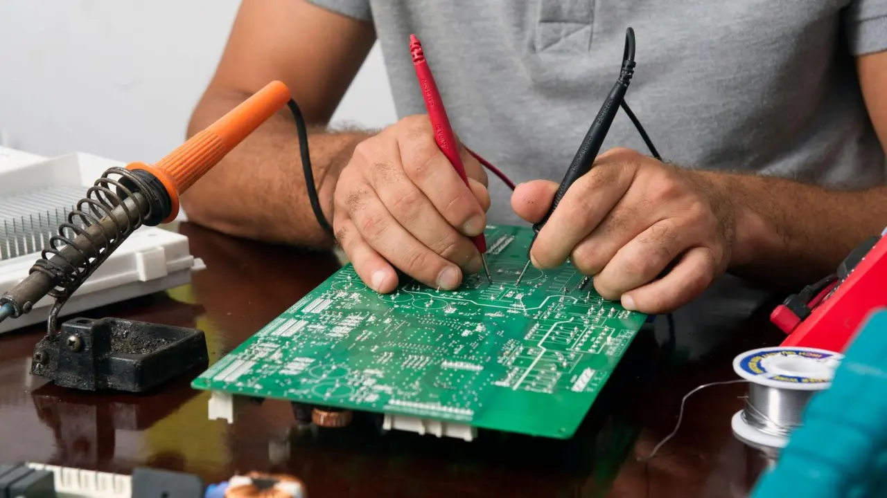
- Touch the red probe to the anode and the black probe to the cathode. Note the reading.
- Reverse the probes, so red is on the cathode and black is on the anode. Note the reading again.
- Compare both readings with the results guide below.
Take your time with the probe placement, because swapping them by accident gives you a false verdict. Keep the band end in mind: the black lead goes there for the forward test.
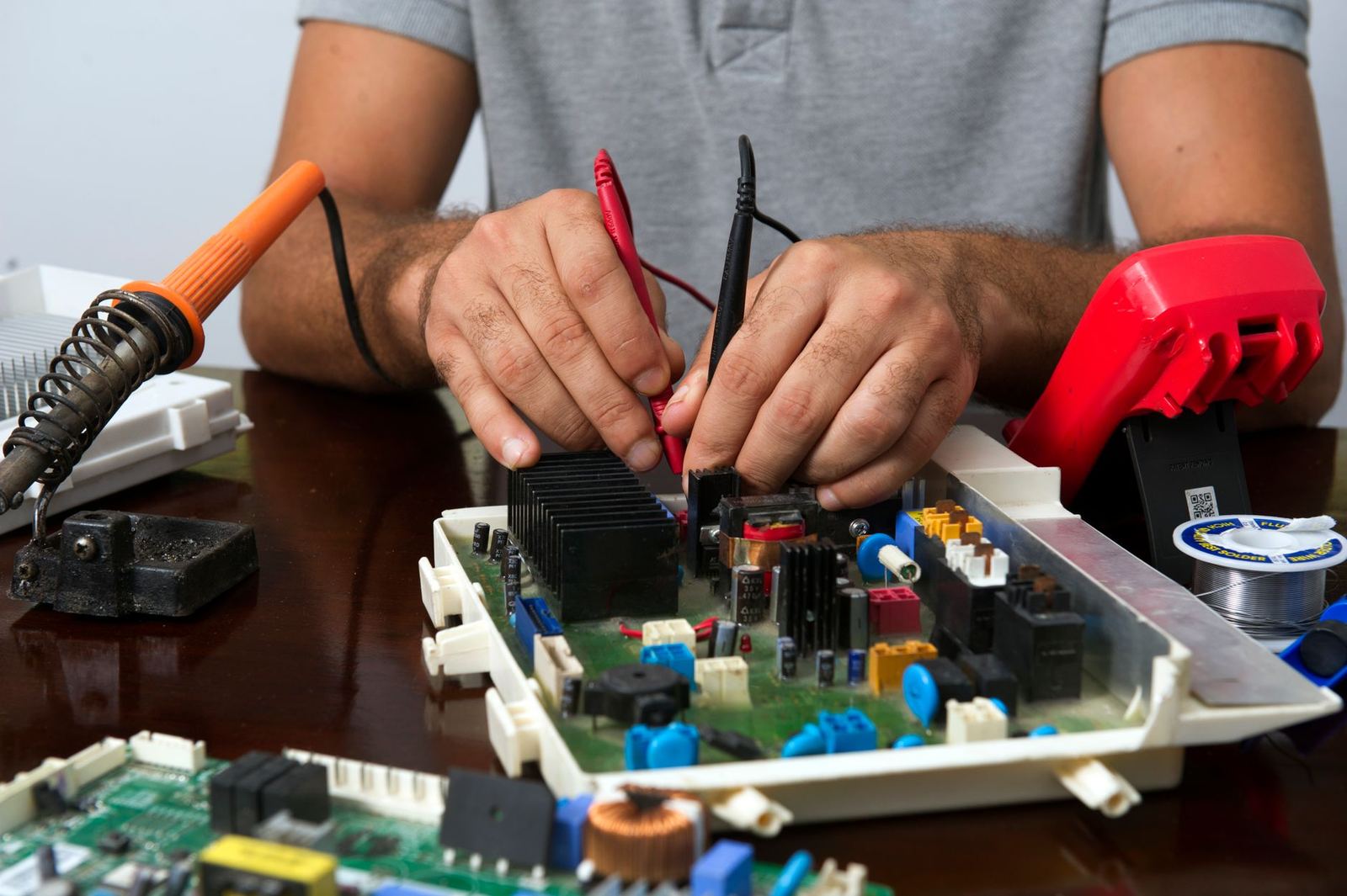
As a worked example, Starting Electronics shows a forward reading of 0.596V on a general-purpose silicon diode and calls it close to the expected 0.6 to 0.7V range. That diode passed.
How to read the results
A good diode conducts one way and blocks the other. Use this list to judge what your meter shows:
- Good: a forward reading around 0.6V to 0.7V, then OL when reversed. Starting Electronics notes that in reality the reading is often below 0.6V.
- Shorted: a reading close to 0V in both directions, per Starting Electronics. eTechnophiles gives a wider band of 0V to 0.4V in both directions.
- Open: OL in both directions, which means no current flows either way.
Some meters show 1 instead of OL on the diode setting to indicate an open circuit, as Starting Electronics points out. Read your meter’s manual if the display looks unfamiliar.
Different semiconductor types read differently. eTechnophiles gives 0.5V to 0.8V for a silicon diode and 0.2 to 0.3 for a germanium diode in forward bias.
If the diode reads like a short but you cannot see why the board misbehaves, the fault may lie elsewhere, and it helps to know how to find a short circuit on a circuit board. If the diode passes, the next suspect could be a capacitor, so it is worth learning how to test a capacitor as well.
Can you test a diode in resistance mode?
Sometimes, but it is the second-best route. eTechnophiles says this method does not give conclusive evidence about the state of the diode, so diode mode is the recommended method.
If you must use it, a good diode shows a forward resistance between 1KΩ to 1MΩ and OL in reverse. Select the highest resistance range for the forward test, and isolate the diode first.
The trouble is that digital multimeters often fail here. Starting Electronics says most do not supply enough voltage in resistance mode to overcome the diode’s forward voltage threshold, typically around 0.6 to 0.7 volts for standard silicon diodes.
You may therefore see these symptoms on a perfectly healthy part:
- OL, or infinite resistance, in both directions.
- No meaningful difference between forward and reverse readings.
- No reading at all, especially on auto-ranging meters.
Testing LEDs, zener diodes and bridge rectifiers
An LED is tested the same way, but its forward reading is higher. Starting Electronics says it may be between 1.8V and 3.3V depending on the colour.
A zener diode is a special case. Diode mode checks forward bias as usual, but reverse testing needs an external voltage above the zener’s breakdown voltage, which a standard multimeter cannot supply, per Starting Electronics.
A bridge rectifier packs four diodes into one package, so test it pair by pair. Identify the two AC pins, the positive (+) pin and the negative (-) pin, then use diode mode with these expected readings from Starting Electronics:
- Red on an AC pin, black on (+): about 0.6V to 0.7V.
- Red on an AC pin, black on (-): OL.
- Red on (-), black on an AC pin: about 0.6V to 0.7V.
- Red on (+), black on an AC pin: OL.
- Between (+) and (-), either way round: OL.
Repeat the AC checks for the other AC pin. Any pair that breaks this pattern points to a failed diode inside the package.
Frequently asked questions
What does OL mean on a diode test?
Show answer
Starting Electronics describes OL as open loop, indicating no current flow. On a good diode you should see it in reverse, as that guide explains.
Which probe goes on which end of the diode?
Show answer
For the forward test, the red probe goes on the anode and the black probe on the cathode, the end marked with a band. Starting Electronics then has you reverse the probes for the reverse test.
Can I test a diode while it is still in the circuit?
Show answer
It is better not to. eTechnophiles says the diode should be isolated from the circuit for accurate readings, so disconnect or remove it if you can.
What reading means a diode is bad?
Show answer
A reading close to 0V both ways suggests a short, and OL both ways suggests an open diode, per Starting Electronics. Either result means the part has failed.
Why does my meter show OL in resistance mode?
Show answer
Many digital meters do not supply enough voltage in resistance mode to turn the diode on, so a healthy diode can show OL both ways, as Starting Electronics notes. Switch to diode mode and test again.