Unsure whether that bulging or suspect part is dead? Here is how to test a capacitor: discharge it fully, then use your multimeter’s capacitance mode or its ohms range and compare the result with the rating.
For the wider picture of fault-finding on boards and appliances, see the electronics repair hub.
| Item | Value |
|---|---|
| Shorted capacitor on an ohms range | A few ohms or less |
| Typical DMM test voltage on ohms ranges | No more than 0.6 V |
| Discharge resistor named in one meter manual | 100 k ohm |
| Example capacitor tolerance | 20% |
| Multimeter capacitance test works best | Above 1 μF |
These figures come from Repairfaq’s capacitor testing guide and Starting Electronics’ multimeter capacitor test. They can change with the meter and the part, so check the sources before you rely on them.
Discharge the capacitor before you touch the probes
A charged capacitor can damage your multimeter or give false readings, according to Starting Electronics. In mains-powered gear, stored charge can also hurt you.
Repairfaq notes that shock risk is real in equipment such as TVs, computer monitors and microwave ovens. A capacitor on a small low-voltage logic board is a very different matter from one in a power supply.
Work through this order every time:
- Unplug the device and remove all power, including batteries where fitted.
- Discharge the capacitor through a resistor. One meter manual quoted by Starting Electronics says to use a 100 k ohm resistor.
- Note the capacitor’s polarity marking before you disturb anything.
- Only then connect the meter.
For extra protection, Repairfaq suggests a pair of 1N400x diodes in parallel with opposite polarities across a DMM’s inputs. A DMM generally supplies no more than 0.6 V on its ohms ranges, so the diodes do not change readings. This trick does not suit a typical analog VOM, which usually supplies too much voltage on the ohms ranges.
Testing with your multimeter’s capacitance mode
A meter that tests capacitors usually has a dedicated capacitance setting marked with a symbol like “μF” or with a capacitor symbol. Check that its range suits the part, because each meter has limits.
As an example, the Amprobe 37XR-A manual quoted by Starting Electronics lists a top range of 400 µF. That meter can’t measure a 1000 µF capacitor.
- Discharge the capacitor fully.
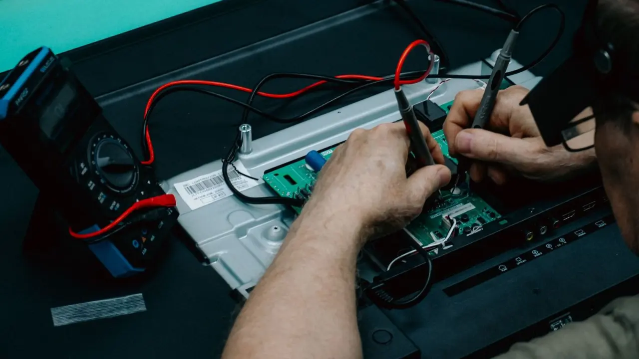
- Set the multimeter to capacitance mode and check which sockets the leads need.
- Connect the probes across the capacitor, matching polarity on an electrolytic.
- Read the display and compare it with the printed value.
Allow for tolerance. Starting Electronics points out that some capacitors have large tolerances, such as 20%, so a reading a little off the label is not automatically a fault.
Capacitance modes have a blind spot. Repairfaq explains that for most applications they do not test anywhere near the normal working voltage, and they do not test for leakage.
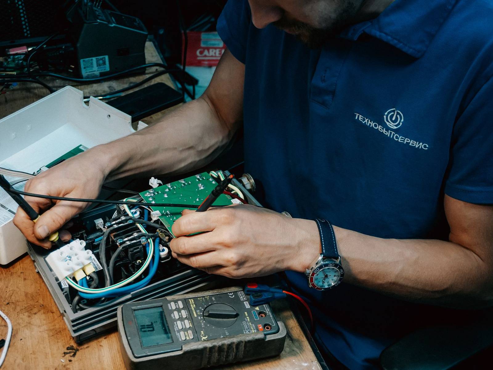
How to test a capacitor with only an ohms range
If your meter has no capacitance mode, you can still watch the capacitor charge from the meter’s own test current. Set the ohms range, connect the probes and watch the reading.
On electrolytics, Repairfaq says you should see the capacitor charge on a high ohms scale with the proper polarity, with the resistance rising until it goes to nearly infinity. What you see tells you the fault:
- Good: the resistance climbs steadily as the capacitor charges.
- Shorted: the reading stays at a few ohms or less and never charges.
- Open: the resistance reads infinite immediately and does not change.
- Leaky: the resistance never goes very high.
Probe polarity matters because meters differ. Repairfaq says red is usually negative with analog VOMs but positive with most DMMs, so mark your meter’s polarity before testing. A marked diode settles it, and the guide on how to test a diode with a multimeter shows the check.
Reading your results
Use this quick comparison of the two methods, based on the table in Starting Electronics.
| Test method | Good capacitor | Bad capacitor |
|---|---|---|
| Capacitance mode | Reading close to the rating | Far below the rating, or no reading |
| Ohms range | Rising resistance | Constant zero, or no movement |
The comparison above follows Starting Electronics’ multimeter capacitor test. Readings differ between meters, so check the source before you rely on it.
In capacitance mode, judge the number against the label rather than expecting an exact match. A reading within a tolerance such as 20% is normal, as Starting Electronics explains, while a value far below the rating or no reading at all points to a failed part.
In ohms mode, you are judging behaviour rather than a figure. A healthy capacitor shows the resistance rising as it charges. A shorted one shows zero or very low resistance, and a leaky one, per Repairfaq, never lets the resistance go very high.
If a result looks strange, rule out the meter first. The same source advises checking your multimeter’s battery and test leads when readings seem off.
Before you condemn the part, run through this short checklist:
- Was the capacitor fully discharged before the probes touched it?
- Were the probes matched to the polarity marking on an electrolytic?
- Was at least one lead free of the circuit, so other components could not skew the reading?
- Does the part sit within your meter’s capacitance range?
If the answer to all four is yes and the result still looks wrong, treat the capacitor as suspect and confirm it with a second method or a more precise meter.
Can you test a capacitor in the circuit?
Sometimes, but it is a compromise. Repairfaq says capacitance testing normally needs at least one lead of the suspect part disconnected for a reasonably accurate reading, or any reading at all.
Newer meters may do a decent job in-circuit, with all power removed and the capacitor discharged. Even so, Starting Electronics warns you may get inaccurate readings due to parallel paths, and recommends testing out of circuit for the most accurate results.
If you have to lift a lead, read up on soldering iron temperature settings first so you do not damage the board.
Where a multimeter test falls short
A multimeter is a good first check, not a laboratory instrument. Keep these limits in mind:
- On small capacitors of 0.01 µF or less, Repairfaq says about all you can test is for shorts or leakage.
- Ceramics under 1 nF often show no result on basic multimeters, according to Starting Electronics.
- The same page says a multimeter capacitor test works best on capacitors above 1 μF.
- Some advanced multimeters can test equivalent series resistance (ESR), a key measure of capacitor health.
When a part passes every test but the equipment still misbehaves, the next step is a dedicated ESR or LCR meter, which is more precise than a multimeter.
Frequently asked questions
Can a multimeter test a capacitor?
Show answer
Yes. Use the capacitance mode if your meter has one, or watch the resistance on a high ohms range. Both methods need the capacitor discharged first.
What does a shorted capacitor read on an ohms range?
Show answer
According to Repairfaq, any capacitor that measures a few ohms or less is bad. It also never charges, so the reading does not climb.
What happens if I test a charged capacitor?
Show answer
It can damage your multimeter or give false readings, per Starting Electronics. Discharge it through a resistor first.
How accurate is a multimeter for testing capacitors?
Show answer
Starting Electronics says most meters with a capacitance mode are accurate enough for general-purpose testing, but not as precise as dedicated LCR meters.